- 您现在的位置:买卖IC网 > Sheet目录218 > CWR06NC105MR (Vishay Sprague)CAP TANT 1UF 50V 20% 2010
�� �
�
�Typical� Performance� Characteristics�
�www.vishay.com�
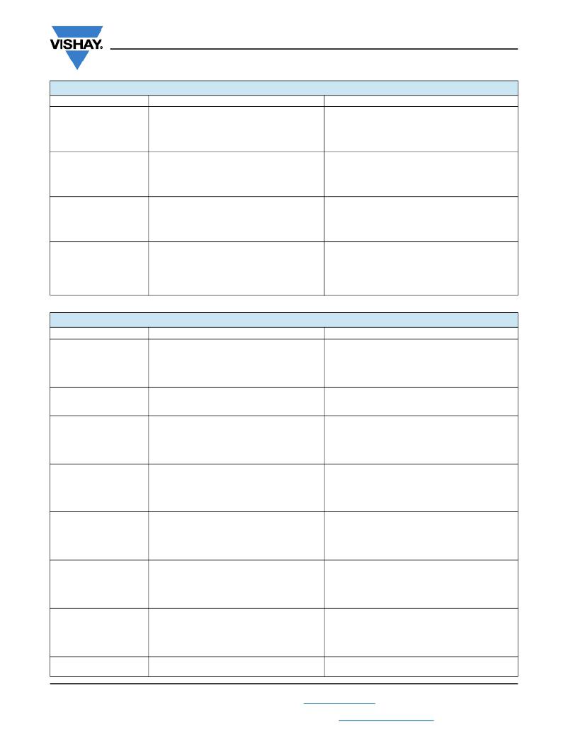
�CAPACITOR� ENVIRONMENTAL� CHARACTERISTICS�
�Vishay� Sprague�
�ITEM�
�CONDITION�
�ENVIRONMENTAL� CHARACTERISTICS�
�Humidity� tests�
�At� 40� °C/90� %� RH� 1000� h,� no� voltage� applied.� ?�
�Capacitance� change� ?�
�Cap.� ?� 600� μF� ?�
�Cap.� >� 600� μF� ?�
�Dissipation� factor�
�?�
�Within� ±� 10� %� of� initial� value� ?�
�Within� ±� 20� %� of� initial� value� ?�
�Not� to� exceed� 150� %� of� initial� ?�
�+25� °C� requirement�
�Temperature� cycles�
�Moisture� resistance�
�Thermal� shock�
�At� -55� °C/+125� °C,� 30� min� each,� for� 5� cycles.�
�MIL-STD-202,� method� 106� at� rated� voltage,�
�42� cycles.�
�Capacitors� are� subjected� to� 5� cycles� of� the�
�following:� ?�
�-55� °C� (+0� °C,� -5� °C)� for� 30� min,� then� ?�
�+25� °C� (+10� °C,� -5� °C)� for� 5� min,� then� ?�
�+125� °C� (+3� °C,� -0� °C)� for� 30� min,� then� ?�
�Capacitance� change� ?�
�Cap.� ?� 600� μF� ?�
�Cap.� >� 600� μF� ?�
�Dissipation� factor� ?�
�Leakage� current�
�Capacitance� change� ?�
�Cap.� ?� 600� μF� ?�
�Cap.� >� 600� μF� ?�
�Dissipation� factor� ?�
�Leakage� current�
�Capacitance� change� ?�
�Cap.� ?� 600� μF� ?�
�Cap.� >� 600� μF� ?�
�Dissipation� factor� ?�
�Leakage� current�
�?�
�Within� ±� 10� %� of� initial� value� ?�
�Within� ±� 20� %� of� initial� value� ?�
�Initial� specified� value� or� less� ?�
�Initial� specified� value� or� less�
�?�
�Within� ±� 10� %� of� initial� value� ?�
�Within� ±� 20� %� of� initial� value� ?�
�Initial� specified� value� or� less� ?�
�Initial� specified� value� or� less�
�?�
�Within� ±� 10� %� of� initial� value� ?�
�Within� ±� 20� %� of� initial� value� ?�
�Initial� specified� value� or� less� ?�
�Initial� specified� value� or� less�
�+25� °C� (+10� °C,� -5� °C)� for� 5� min�
�MECHANICAL� PERFORMANCE� CHARACTERISTICS�
�TEST� CONDITION�
�CONDITION�
�POST� TEST� PERFORMANCE�
�Shear� test�
�Apply� a� pressure� load� of� 5� N� for� 10� s� ±� 1� s�
�horizontally� to� the� center� of� capacitor� side� body.�
�Capacitance� change� ?�
�Dissipation� factor� ?�
�Leakage� current�
�Within� ±� 10� %� of� initial� value� ?�
�Initial� specified� value� or� less� ?�
�Initial� specified� value� or� less�
�There� shall� be� no� mechanical� or� visual� damage� to�
�capacitors� post-conditioning.�
�Substrate� bend�
�Vibration�
�With� parts� soldered� onto� substrate� test� board,�
�apply� force� to� the� test� board� for� a� deflection�
�of� 3� mm,� for� a� total� of� 3� bends� at� a� rate� of� 1� mm/s.�
�MIL-STD-202,� method� 204,� condition� D,� 10� Hz� to�
�2000� Hz,� 20� g� peak�
�Capacitance� change� ?�
�Dissipation� factor� ?�
�Leakage� current�
�Capacitance� change� ?�
�Dissipation� factor� ?�
�Leakage� current�
�Within� ±� 10� %� of� initial� value� ?�
�Initial� specified� value� or� less� ?�
�Initial� specified� value� or� less�
�Within� ±� 10� %� of� initial� value� ?�
�Initial� specified� value� or� less� ?�
�Initial� specified� value� or� less�
�There� shall� be� no� mechanical� or� visual� damage� to�
�capacitors� post-conditioning.�
�Shock�
�MIL-STD-202,� method� 213B� shock� (specified�
�pulse),� condition� I,� 100� g� peak�
�Capacitance� change� ?�
�Dissipation� factor� ?�
�Leakage� current�
�Within� ±� 10� %� of� initial� value� ?�
�Initial� specified� value� or� less� ?�
�Initial� specified� value� or� less�
�There� shall� be� no� mechanical� or� visual� damage� to�
�capacitors� post-conditioning.�
�Resistance� to� solder� heat�
�?� Recommended� reflow� profiles� temperatures�
�and� durations� are� located� within� the� Capacitor�
�Series� Guides�
�Capacitance� change� ?�
�Dissipation� factor� ?�
�Leakage� current�
�Within� ±� 10� %� of� initial� value� ?�
�Initial� specified� value� or� less� ?�
�Initial� specified� value� or� less�
�?� Pb-free� and� lead-bearing� series� caps� are�
�backward� and� forward� compatible�
�There� shall� be� no� mechanical� or� visual� damage� to�
�capacitors� post-conditioning.�
�Solderability�
�MIL-STD-2002,� method� 208,� ANSI/J-STD-002,�
�test� B.� Applies� only� to� solder� and� tin� plated�
�terminations.� ?�
�Capacitance� change� ?�
�Dissipation� factor� ?�
�Leakage� current�
�Within� ±� 10� %� of� initial� value� ?�
�Initial� specified� value� or� less� ?�
�Initial� specified� value� or� less�
�Does� not� apply� to� gold� terminations.�
�There� shall� be� no� mechanical� or� visual� damage� to�
�capacitors� post-conditioning.�
�Resistance� to� solvents�
�MIL-STD-202,� method� 215�
�Capacitance� change� ?�
�Dissipation� factor� ?�
�Leakage� current�
�Within� ±� 10� %� of� initial� value� ?�
�Initial� specified� value� or� less� ?�
�Initial� specified� value� or� less�
�There� shall� be� no� mechanical� or� visual� damage� to�
�capacitors� post-conditioning.�
�Flammability�
�Encapsulent� materials� meet� UL� 94� V-0� with� an�
�oxygen� index� of� 32� %.�
�Revision:� 03-Feb-14�
�3�
�Document� Number:� 40088�
�For� technical� questions,� contact:� tantalum@vishay.com�
�THIS� DOCUMENT� IS� SUBJECT� TO� CHANGE� WITHOUT� NOTICE.� THE� PRODUCTS� DESCRIBED� HEREIN� AND� THIS� DOCUMENT�
�ARE� SUBJECT� TO� SPECIFIC� DISCLAIMERS,� SET� FORTH� AT� www.vishay.com/doc?91000�
�发布紧急采购,3分钟左右您将得到回复。
相关PDF资料
CWR15FK225KCLC
CAP TANT 2.2UF 10% 10V 0603
CWR29KC336KCXC
CAP TANT 33UF 25V 10% 2721
CWSB21AA2H
SWITCH ROCKER DPST 6A 250V
CWSB21DADF
SWITCH ROCKER DPST 9A 125V
CWSC21JDADS
SWITCH ROCKER DPST 9A 125V
CX2016DB27000D0GEJZ1
CRYSTAL 27.000MHZ 8PF SMD
CX2016DB40000D0FLJZ1
CRYSTAL 40.000MHZ 8PF SMD
CX2520DB20000D0FLJZ1
CRYSTAL 20.000MHZ 8PF SMD
相关代理商/技术参数
CWR06NC105MR/TR
制造商:Vishay Intertechnologies 功能描述:Cap Tant Solid 1uF 50V E CASE 20% (5.08 X 2.54 X 1.27mm) SMD (0.01%FR) 6 Ohm 125C T/R 制造商:Vishay Sprague 功能描述:CAP 1UF 50VDC 20% 5.08 X 2.54 X 1.27MM SMD 0.01% - Tape and Reel
CWR06NC105MRA
制造商:Vishay Sprague 功能描述:CAP 1UF 50VDC 20% 5.08 X 2.54 X 1.27MM SMD 0.01% - Bulk
CWR06NC105MRB
制造商:Vishay Sprague 功能描述:CAP 1UF 50VDC 20% 5.08 X 2.54 X 1.27MM SMD 0.01% - Bulk
CWR06NC105MRC
制造商:Vishay Sprague 功能描述:CAP 1UF 50VDC 20% 5.08 X 2.54 X 1.27MM SMD 0.01% - Bulk
CWR06NC154MC
制造商:Vishay Sprague 功能描述:CAP 0.15UF 50VDC 20% 2.54 X 1.27 X 1.27MM SMD 0.01% - Bulk
CWR06NC154MM
制造商:Vishay Sprague 功能描述:CAP 0.15UF 50VDC 20% 2.54 X 1.27 X 1.27MM SMD 1% - Bulk
CWR06NC154MP
制造商:Vishay Sprague 功能描述:CAP 0.15UF 50VDC 20% 2.54 X 1.27 X 1.27MM SMD 0.1% - Bulk
CWR06NC155JB/TR
制造商:Vishay Sprague 功能描述:CAP 1.5UF 50VDC 5% 5.59 X 3.43 X 1.78MM SMD 0.1% - Tape and Reel